 
Chapter 1
The Wood Hydraulic Hoist Company
The son of a steamboat captain, Iowa-born Garfield Arthur Wood had a lifelong love of boating, and speedboat racing victories would make him world famous in his later years. The young Wood was trained as a marine engine mechanic, and was known early on as a creative inventor. His most important invention, and the one that would earn him enormous wealth, was a practical hydraulic lifting hoist that he developed to replace mechanical types used on early dump trucks. This laborsaving truck accessory arrived at the perfect time, just as motor vehicles were replacing horse carts in cities and towns across America and the industrialized world. When transporting bulk loads such as rock, dirt and coal, a more efficient means of unloading this material was needed.
The earliest dump trucks had used hand-cranked mechanical hoists, which required a great deal of human strength to operate. Wood was reportedly inspired by the sight of two men struggling to unload a dump bed full of coal in the city of St. Paul, Minnesota in 1911. That very same truck was eventually fitted with Wood's prototype hydraulic hoist for trials, easily lifting and dumping the 'load' of people who had climbed inside the bed for the test! The owner of the truck was duly impressed, ordering hoists for his entire fleet and becoming the first Gar Wood customer. The Wood hoist was sold as a package consisting of a pressure pump, storage tank, control valve and the working hydraulic ram itself. Power to turn the pump was simply tapped from the vehicle engine, which was typically idling while a truck was being unloaded.
Wood's powerful hydraulic hoist rapidly eclipsed the manually operated truck bed lifts. He not only secured patents for his invention, the first in October of 1912, but founded The Wood Hydraulic Hoist and Body Company at Minneapolis, Minnesota, for the manufacture of a complete line of hoists and truck equipment. By the 1920s, the company had moved to Bellevue Avenue in the city of Detroit, Michigan, the heart of motor vehicle production in America. Mr. Wood's brothers came with him, and were involved with all aspects of the business. Gar Wood became a young millionaire, which enabled him to entrust the company to his younger brother Logan Wood, while he pursued his true passion for boat racing. Between 1916 and 1933, Gar went on to become a racing champion, establishing new water speed records aboard his Miss America boats. In 1930, he established Gar Wood Inc., at Marysville, Michigan for regular production of boats for sale to the public.
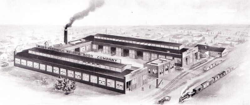
The Wood Hydraulic Hoist and Body Company on Bellevue Avenue in Detroit, Michigan
A Wood model G-29 enclosed garbage body from 1920, capacities were 2-7 cubic yards with six loading doors
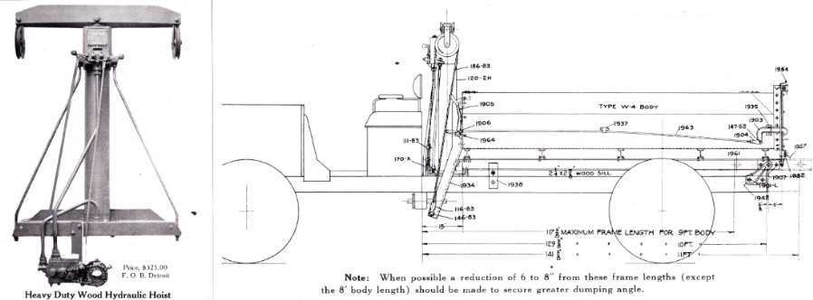
Wood hydraulic hoist was mounted between the truck cab and body.
Vertical cylinder with crossbar was attached to the front of the dump body by cables.
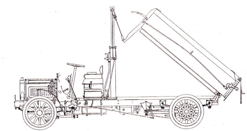
Hoist cylinder extends to tip dump body
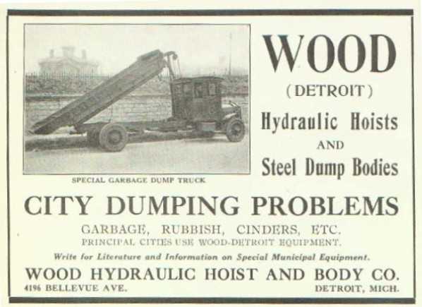
Advertisement for garbage bodies from 1921
After retirement from racing in 1933, Wood returned to a more active role in his manufacturing company, which was thriving despite the difficulties of the Great Depression. It became the world's largest manufacturer of truck equipment, and added other product lines under the new company name Gar Wood Industries. Truck bodies became increasingly specialized, often custom-built to the users specifications. Gar Wood expanded Detroit operations again with a new factory on Riopelle Street, building an endless variety of refuse bodies and trailers. Logan Wood was still managing the company, but it was another of Gar's brothers, George Benton Wood, who would figure most prominently in development of refuse equipment.
However, the compactor truck had yet to take hold in American cities, and specialized hand-loaded collection bodies were typically employed to meet the collection needs of individual municipalities and a three-tiered waste steam. Garbage, which is primarily composed of food waste, was often collected separately and rendered or used as hog feed. Bodies to collect garbage needed to be watertight, to prevent liquid from leaking out. Seamless 'dove-tailed' dump beds were often used in this application. Fully enclosed garbage bodies were later introduced, which improved public appearance and minimized odors. Consisting of wood, paper and metal, rubbish was typically burned or buried, though metals were sometimes salvaged. Rubbish tended to be bulkier than garbage, and thus required much larger bodies for increased capacity. Many cities did not provide regular rubbish collection, leaving its disposal to the property owner. Ash was the third leg of the waste stream, and made up a large part of municipal collections where coal was the primary heating fuel. Ash was often re-used as a road abrasive during the winter months. Because of the dust created, ash was difficult to handle in any circumstances. Where ash and rubbish were co-mingled, a fire hazard was always present to the collectors.
During the early years, Wood Hydraulic built all manner of truck bodies, including models specifically for garbage and rubbish collection. As a manufacturer of quality hydraulic pumps and cylinders, they also supplied components to other body builders, some of which developed "self-loading" models, which eased the burden of collection crews. The Colecto was one of the earliest self-loading refuse trucks, and some models are known to have used Wood hoists for both the bucket and body lifts. Despite the growing demand for collection vehicles, Gar Wood had yet to offer a mechanical refuse loader or packer truck during the early 1930s. And despite the availability of self-loaders like the Colecto and later by the Leach Refuse Getter, garbage and refuse removal remained primarily a hand-loaded operation in most American cities. The hydraulic hoist had definitely eased the work of unloading refuse trucks, but the physically demanding, and often-dangerous work of loading them still remained.
Eventually, hydraulic refuse packers would find favor in America, and Gar Wood Industries would be at the forefront of their development and the undisputed industry leader for many years to come. Although Gar Wood himself never designed a refuse packer, that does not in the least diminish his critical contribution to the industry. His hydraulic hoist has been the key component of virtually every major development within the refuse body industry, and all manner of other power-operated equipment. A hydraulic cylinder can remotely power almost any device that is raised, swings, slides or tilts Earth moving equipment, cranes, fire-fighting trucks, automotive braking and aircraft control systems are but a few applications that have realized the benefits of mobile hydraulic power.
During the 1930s, Gar Wood Industries was in the enviable position of selling a wide variety of hand-loaded refuse and garbage bodies even as they were developing their own compaction-type unit. This established relationship with municipalities would yield sales opportunities for their more advanced packer bodies when they arrived on the market, while still offering traditional equipment to users who preferred hand loading. This strategy would pay great dividends, as the changeover to packer-type units would be a gradual process that would take many years.
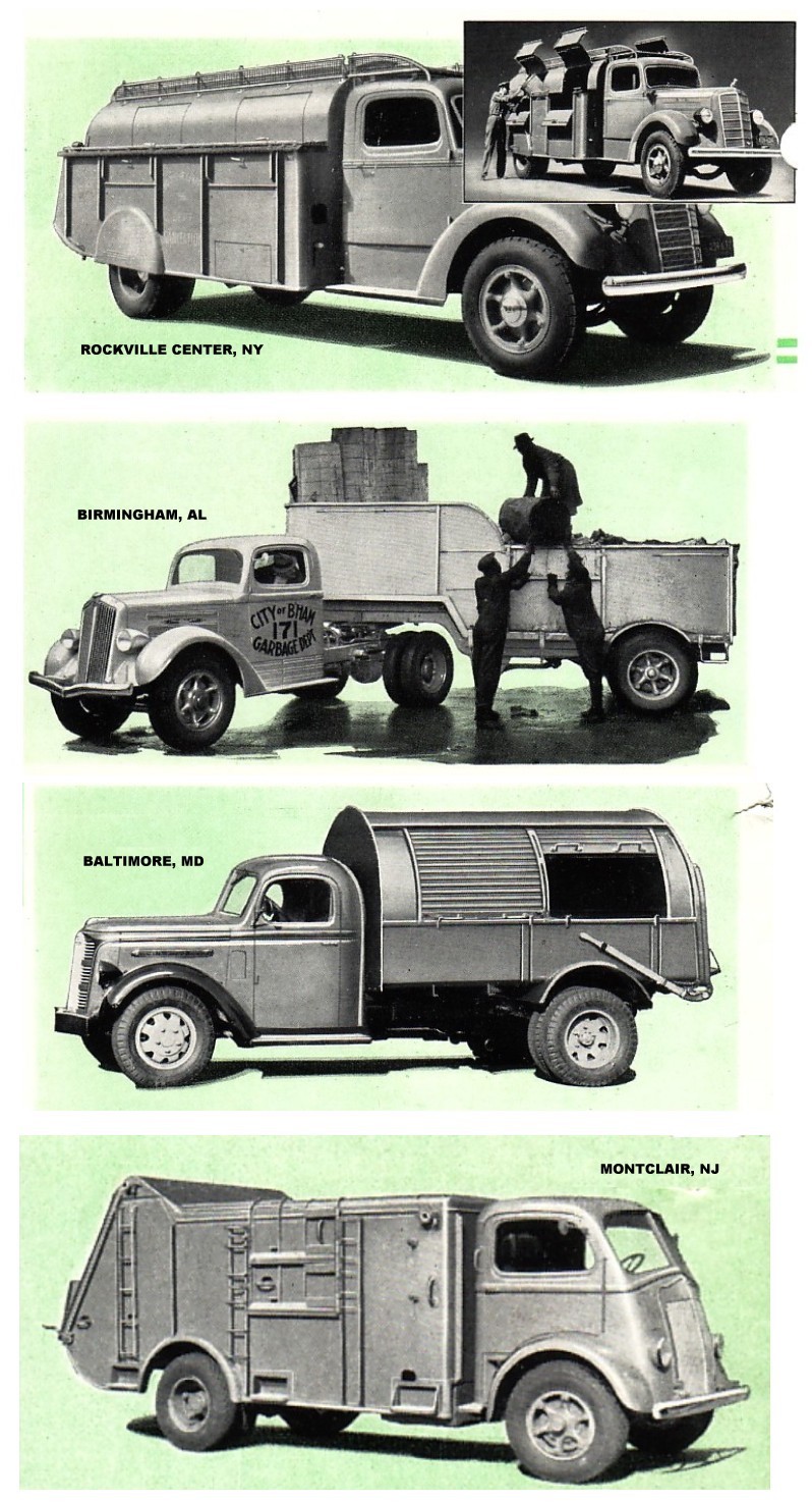
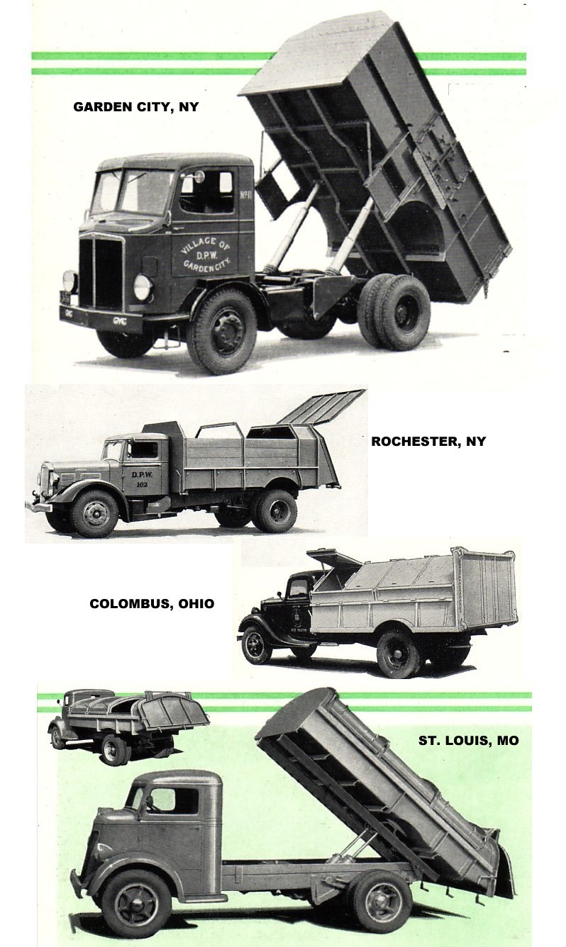
GAR WOOD COLLECTION BODIES OF THE 1930s
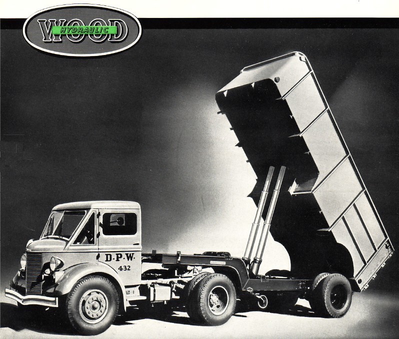
High-capacity Gar Wood rubbish body with twin telescopic hoists
SIDEBAR: BASIC HYDRAULIC POWER
When Gar Wood invented his hoist in 1910, the concept of hydraulics, or fluid power, was not exactly new technology. The centuries-old mill wheel, harnessing the movement of falling water is probably the most basic application of hydraulic power. Mill wheels came with the Europeans to the New World, and dotted the American landscape well into the industrial revolution. But it was French mathematician Blaise Pascal (1623-1652), who is credited with defining the principle of hydraulics;
In a fluid at rest in an enclosed vessel, pressure changes applied
to any point are transmitted equally to all points in that fluid.
To understand basic hydraulic power transmission using Pascal's Law, one could imagine a simple, theoretical lift. Two cylinders, one large and one small, are connected at their bases with a length of tubing and filled with water. Within each cylinder, we place a circular plate or piston which fits closely against the cylinder walls, yet is still capable of sliding up and down within the cylinder bore. For this lift, let us say that the surface area of the small piston measures one square inch, while that of the large piston measures two square inches.
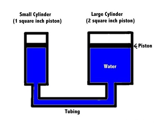
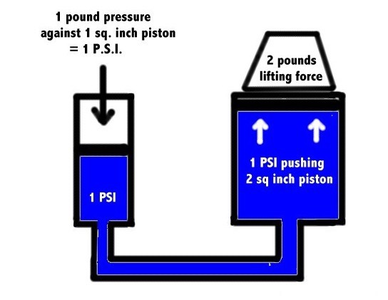
If we were to apply a pressure of one pound on the small piston by pushing down on it with our finger, the water below would be forced out of the small cylinder under pressure. Since the surface area of the small piston is one square inch in size, we transmit a force of one pound per square inch, or 1 PSI, through the water below.
The water is forced through the connecting tube and into the large cylinder, and enters at a pressure of 1 PSI, forcing the larger diameter piston to move upward. Since this piston has a surface area of two square inches, and the incoming water is acting against it has a pressure of 1 PSI, the large piston would be capable of lifting a two-pound weight (1 PSI x 2 square inches= 2PSI total lifting capacity), effectively doubling the force we originally applied to the small piston. This force multiplication could be made even greater, either by increasing the force (PSI) acting on the piston of the small cylinder, and/or increasing the dimensions of either cylinder.
One of the first practical applications of hydraulic power in industry was the stationary press, used for a wide variety of manufacturing processes and often powered by compressed water that was either supplied municipally, or by pumps at the factory site. The development of cup seals, which ride between the piston and cylinder, made reliable and leak-free hydraulic rams possible. Why would industry choose hydraulics, one might ask? Because the alternative power means were mainly mechanical, using engines or motors to drive gears, chains, belts and cables that were subject to high wear and required far more maintenance. Fluid is capable of transmitting power over long distances, and transmission piping could be shaped to fit unusual installations or routed underground. If hydraulic power was practical in stationary factory applications, it was only logical that it would find many uses in motor vehicles, where space and weight were prime considerations.
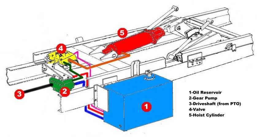
Gar Wood's genius was in applying this established technical concept to a practical working device; the dump truck hoist. Oil, instead of water was used as the transmission fluid, because of its corrosion resistance, lubricating qualities and resistance to freezing. This Gar Wood under-body dump hoist from the 1950s (shown below) illustrates the concept ably as it is commonly used today:
Note: The hydraulic system described below is generic for the purpose of illustrating the basic principles of operation. There are many variations possible in systems as actually built.
Idling (PTO engaged, hoist at rest)
A reservoir of oil is stored in a large steel tank (1) on the truck frame. A gear type pump (2) is turned by the drive shaft (3) of a power take-off (PTO) from the vehicle transmission. The pump siphons oil from the reservoir (blue pipe) and compresses it to a pressure of 1,000 PSI. However, with the pump turning, and the control valve (4) in neutral, there is no place for this oil to go, and the system pressure quickly rises. The rise in pressure opens a pump relief valve that shunts the unused oil flow directly back into the reservoir (red pipe). Without the relief valve, the system components would be in danger of bursting due to excessive pressures.
Hoisting (Extending the hoist)
To begin the hoist cycle, the operator moves the control valve (4) to the raise position, which directs the high-pressure fluid to flow from the pump (2, green pipe) to base of the 7-inch diameter hoist cylinder (5, orange pipe). The incoming oil then pushes against the piston within the cylinder at a pressure of 1,000 PSI. The hoist piston surface area is about 38 square inches, which results in a usable lifting force of 38,000 pounds (1,000 PSI x 38 square inches). A heavy steel rod attached to the top of hoist piston extends outward as oil is forced through the cylinder, raising the hoist gear and dump bed. Once the hoist is fully extended, and with the pump continuing to force oil into it, the pressure again rises in excess of 1,000 PSI. This pressure spike opens the pump relief valve, discharging excess oil back into the reservoir (1), as long as the control valve is held open and the hoist is fully extended.
Holding (Hoist extended and locked in place)
With the hoist extended, operator moves the control valve (4) back to the neutral position, trapping the oil within the hoist cylinder (5) and the orange pipe, thus preventing backward movement of the piston and holding the dump bed in the raised position. The oil is basically non-compressible, and can hold an infinite amount of weight, so long as the cylinder, valve and piping can withstand the pressure. Since the pump continues turning, unneeded fluid is once again shunted back into reservoir through the relief valve. The hoist may be held partially extended, if the operator releases the control valve lever before the hoist has reached its maximum extension.
Lowering (Hoist returned to resting position)
Operator reverses valve (4) allowing fluid to flow out of hoist cylinder (5) and back through the valve, and then out a return line (violet pipe) connected to the reservoir (1). The weight of the load being lifted (the heavy truck body) forces the oil back out of the hoist, lowering itself by gravity. A one-way flow restrictor may be used in the orange line, which keeps fluid from escaping the hoist too rapidly, causing the dump bed to descend slowly without damaging the vehicle. While lowering, the idling pump (2) continues to dump its unneeded fluid back into reservoir, until PTO is disengaged.
This is called a single-acting hoist cylinder, since it uses pressure only in one direction (to extend), and relies on gravity to retract. Double-acting type cylinders may be used in other applications, where pressure is needed in both directions.
Relief valves protect the system components by limiting pressures to a predetermined value. They are automatic, and may be used throughout the hydraulic system wherever necessary. They not only protect against operator error, but also against mechanical failures and excessive loads.
The reservoir serves as an oil supply, as well as cooling the oil as it circulates within the tank. High pumping pressures create heat, which is damaging to components. Baffles are usually incorporated within the reservoir to provide maximum detention time for the incoming oil, and a filter removes impurities from outgoing fluid headed for the pump.
It is from this basic arrangement that hydraulic engineers build the modern refuse truck. More valves and piping may be added to work other components such as tailgate lifts, packer cylinders, lift arms, sliding doors, and rotary motors. Rods, cables or even pilot-operated circuits may be used to remotely operate control valves. Direct-drive pumps, coupled to the engine crankshaft, are often used in place of the transmission PTO. In spite of the complexity of modern refuse equipment, the basic concept of truck hydraulics illustrated here has changed very little in the 100-plus years since Gar Wood's demonstration in St. Paul, Minnesota.
|


7/30/14
© 2014 Eric Voytko
All rights reserved
Photos from factory brochures/advertisements except as noted
Logos shown are the trademarks of respective manufacturers
|
| |